
Issue 98
Issue 98
Scanned and Prepared by Grant/NQ5T
The Golden Era of AM
Among the many facets of amateur AM, nostalgia and fascination with vintage radio are responsible for a lot of interest in the mode today. Originally, the "golden days" of AM were thought of as occurring in the 1930's. By then, a high degree of perfection had been achieved in radio technology, and the underlying theory of radio and circuit operation was well understood by engineers. Reliable operation, high fidelity audio and worldwide communication were readily possible for those who could afford the materials and had the expertise to build the equipment. Superheterodyne receivers, stable crystal controlled transmitters, class-B audio amplifiers, high quality audio transformers and microphones, dynamic speakers, and a wide variety of commercially available tubes made it all possible. This period of radio was long remembered with fondness, well past the 1960's.
For about a decade, beginning in the mid 1960's, amateur interest in AM dropped to such a low level that mainstream ham radio ceased to even recognize its existence as a legitimate facet of the hobby. In the mid 1970's, when interest in AM began to reappear, nostalgia was less a factor than a quest for high quality sound and a level of technology that still allowed the average ham some hands-on experience with the innards of transmitters. Inevitably, as use of the mode became more widespread, many old timers remembered how much fun they had with AM in the 1950's, encouraging still more AM activity, which attracted quite a few newcomers as well, particularly those who found SSB boring. Today, nostalgia has become one of the major attractions to AM.
For today's AM community, the 1930's are too remotely in the past and beyond most of our memories. It doesn't take a lot of listening to AM QSOs to discover that the "golden days" have shifted to the 1950's, with present-day nostalgia revolving around Johnson Vikings, Globe Kings, DX-100's and the vast array of commercially manufactured receivers of the 1950's, the Collins 75A-4 considered the ultimate in the minds of many.
As far back as the early 1960's, the term "appliance operator" had already been coined by the original old timers who had always, probably more by necessity than by choice, homebrewed their own transmitters. They were alarmed by the proliferation of commercially built AM equipment; the era of the SSB appliance operator would not arrive until the mid 1960's with the advent of poor quality but affordable SSB transceivers like the Swans, Galaxies and Heathkit "Hot Water" series.
No matter how much some of us now deride the SSB appliance operators, homebrew AM transmitters are not often heard on the air today. Many AM'ers are reluctant to make even simple modifications to their 50's gear to improve signal quality out of fear of spoiling the value of the equipment as "pure vintage". In fact, quite the opposite often happens as owners of second hand rigs seek authentic components to restore their modified equipment back to "the original".
The first "golden era" of AM began about 1933, with the advent of class-B modulators, superhet receivers and the return of 160 meters as a popular phone band. This period came to an abrupt halt in 1941 with Pearl Harbor, lasting less than a decade. Many of us fail to realize that AM in the 30's was almost as much in the minority as it is today, since a depression was going on and the vast majority of hams were lucky to afford a regenerative receiver and low power self excited oscillator transmitter for CW. Most hams operated CW only, and a prevailing attitude in ham radio was that "phone men" were "lids" who cluttered up valuable spectrum space with splatter and distorted signals, an idea somewhat reminiscent of recent mainstream attitudes about AM.
The second "golden age" of AM began in the mid 1950's with the advent of commercial rigs such as the Vikings and DX-100. CW had remained dominant until this moderately priced commercially built or kit-form AM equipment came along, despite the existence of numerous homebrew AM rigs built largely from WWII surplus. In less than a decade, this "second wave" of AM would be eclipsed by the advent of SSB.
AM began to return to the ham radio scene in the mid 1970's, and grew in popularity to the point that the first AM-oriented publication, W2NRM's original Press Exchange appeared in 1980. It is now 12 years later, with two AM publications in operation, and AM is at long last gaining some long-deserved recognition by mainstream amateur radio as having a legitimate place in the hobby.
The popularity of AM today is nowhere near what it was in the late 1950's, but the duration of the present "third wave", if measured only by the existence of AM publications, has already exceeded by several years the length of the "golden era" of the 1930's, and has lasted at least as long as the post WWII/pre-SSB boom period.
The 1950's was a time in history of unprecedented popularity of AM, and was a peak period of AM activity. However, in reality, this was the beginning of a massive changeover in amateur radio from being predominantly CW-oriented to voice-oriented, a change that was largely the result of the elimination of the old "Class-A" phone restrictions and the opening of 40 metres to voice operation. It just so happened that this shift began to occur before SSB achieved widespread popularity. The poor audio quality of many 1950's AM rigs and the rapid and almost universal acceptance of SSB by the amateur community indicate that amateurs, as a whole, never were interested in high fidelity AM as a distinctive method of voice communication. The present day popularity of AM as an option of choice has lasted more than a decade and is still going strong. Perhaps it would be appropriate to declare that the "golden era" of AM is NOW!
-K4KYV
Ten-Tec Developing AM Boards for Their Transceivers?
Rumor has it that Ten-Tec may be developing an AM board for some of their transceivers. In early February, some AM'ers on the top end of 40 heard a high quality AM signal from a station claiming to be talking on a Paragon, using an AM board built at the Ten-Tec factory. The operator mentioned something about the board being under development and that he was experimenting with it on the air. Some of the 40 metre AM'ers called the factory and reportedly were told that the AM board was indeed under development for a commercial customer, and that it would probably become available to amateurs who order it directly from the company.
If this story is true, it is a significant development since Ten-Tec has in
the past displayed a decidedly negative attitude towards AM and indicated that,
as a matter of policy, they were not willing to include the AM transmit mode on
their transceivers. Many hams would welcome the availability of AM
capability on a U.S. made amateur radio product, especially considering
Ten-Tec's excellent record on providing service, parts and technical advice for
the equipment they manufacture.
Open Forum
Editor, The AM Press/Exchange:
A proposal seems to be overlooked which may affect those of us with vintage amateur equipment. The ARRL is proposing for the next WARC to move the 40-metre band downwards to 6.9-7.2 mc. As an ARRL life member I wrote HQ concerning my displeasure with the proposal. The unsympathetic response indicated I should modify my equipment. I am not inclined to mess with modifying my perfectly useful Ranger I. If this proposal is enacted, I and many other amateurs will lose some usefulness of equipment and access to frequency privileges.
Steve Putman, N8ZR
Story Behind Recent Petition to Ban AM
Or, Things Aren't Always What They Seem to Be
by John Morehead, N9HRS
You probably read in Issue 97 of The AM Press Exchange that the FCC dismissed another Petition for Rulemaking requesting that AM be banned on frequencies below 28 MHz.
In fact, I was reading the story while listening in on a 75M AM QSO, when I heard it mentioned that the petitioner had just put an AM rig on the air.
My curiosity was aroused. Had my ears deceived me? Had this anti-AMer concluded that "If you can't beat 'em, join 'em." I decided to investigate.
I spoke with Scott Schoenleben, N4UAD, the anti-AM petitioner, and what he had to say was very interesting.
While I may not agree with all of Scott's statements regarding AM, I do feel that what motivated him to put forth the petition warrants some consideration. After all, we're not invulnerable, as the recent AM power reduction so dramatically reminds us.
To start with, Scott's a ham who's intelligent, friendly and well-mannered (attributes lacking with many other anti-AMers). How do I know? I've spoken with him and have heard others' observations about him.
"I wrote the petition because of what was going on, primarily on 75 meters," said Scott. Specifically, he objected to "AM stations who would come in on top of other existing conversations."
To put things in perspective, Scott operates on 3.875, which has been a bit outside the traditional AM "window". Recently, though, many of the 3.875 regulars have discovered the "joys of AM"
Scott feels "it is poor practice to put on the widest mode possible," during peak times, especially on 75.
Needless to say, there were some "territorial" problems that precipitated Scott's petition. He was especially concerned by certain groups of AMers who would "zero beat 3.875 and tell other AMers in the group to listen on upper ''.
Since writing the petition, circumstances have influenced Scott to where he now has a DX-60 on the air and might not pass up a bargain on a nice 32V.
To start with, some of the 3.875 regulars have become AM active, although primarily after midnight. Scott has noticed that "some of the finest audio is heard on AM ham radio."
After further listening, Scott realized his petition was "addressing just a small percentage of AM operators." He said his complaint was "not against the mode - just poor operators" he happened to encounter who were using the AM mode.
Scott said that his "thinking has changed since writing the petition." However, Scott strongly feels that "if we don't self-police, someone will come around and do it for us through legislation."
What can we learn from this? To start with, AM is a distinctive mode. When someone notices bad operating by an AMer it is easy to form stereotypes that all AMers are rude, discourteous operators. Lets face it, there are a lot less of us than them. So, when one of us creates a bad image it disproportionately creates ill will against all of us.
"In retrospect," said Scott, "I doubt I would send in the petition today."
Another positive: the FCC's dismissal of Scott's petition is just one more affirmation on the record to support AM.
Therefore, if you hear N4UAD on AM give him a call and reconfirm what an
enjoyable mode and nice group of hams he's finally discovered.
open forum
Editor, AM Press Exchange,
The March 1992 issue of QST contained a letter written by myself regarding AM operation. Although much of the content was edited by the ARRL, I was pleased to see AM being recognized. However, a statement was made that WAS NOT in my original letter, that being the comment regarding the goal of spectrum efficiency.
Although editing is sometimes necessary, nothing should be added to the original. To set the record straight, enclosed is a copy of the original letter sent to the ARRL, 73,
W4KYL
RD 1 Box 10 B
Little Meadows, Pa. 18830
13 October 1991
Brian Battles, WS1O
Copy Editor
ARRL
Newington, Ct. 06111
Dear Sir,The Pennsylvania QSO Party is in full swing as I type this letter. As usual, those of us who prefer to operate AM have been constantly interfered with by SSB operators who refuse to recognize our right to operate. Most AM operators stay within an exceptionally narrow frequency range. Most SSB operators recognize these "AM Windows" and stay away from these frequencies. Unfortunately, many SSB operators are unaware of these "gentlemen's agreements" and intrude innocently. Their lack of knowledge regarding amateur radio, indeed, radio in general, is demonstrated when they indicate that the carrier they heard (and zero beated so they were not interfered with!) was thought to be someone tuning up! Don't you SSB'ers listen before you transmit?
The problem of not knowing about "AM windows" could be alleviated it the ARRL would change its position and publish, AS A SERVICE TO ALL AMATEURS, the location of these segments of AM operation. In spite of what the ARRL would like to believe, AM operation is growing ...both from old timers returning to AM and newcomers discovering another facet to the hobby.
Respectfully
John Martin
W4KYL
Life Member
COMMON AM FREQUENCIES
2 Meters: 144.4 Mhz 6 Meters 50.4 Mhz 10 Meters 29.0 to 29.2 Mhz 12 Meters 24.985 Mhz 15 Meters 21.4 to 21.45 Mhz 17 Meters 18.150 Mhz 20 Meters 14.286 Mhz 40 Meters 7.160 Mhz, 7.195 Mhz, 7.290 to 7.3 Mhz 75 Meters 3.870 to 3.890 Mhz 160 Meters 1.885 Mhz, 1.945 Mhz
Please note that on several bands, only ONE frequency is used.
1025 W. Parr Ave.
Campbell, CA 95008
Jan 21,1991
Greetings Don: From the home of California where they often use a gallon to talk next door.
Re: Front Page article on Dismissed AM Petition
This party doesn't think much of Scott's petition as he left out a very important part. Methinks he isn't quite carrying his petition in banning a modulated signal to its logical conclusion. The second paragraph shows this fault up to a great degree and I do not see how he failed to recognize his fallacy.
In order to open up the spectrum to a greater number of users, he should have stated "Ban ALL forms of Modulation". He as well as any other proposer of limiting or banning AM modulation, knows the well known fact that several CW signals can occupy the signal taken up by a Single Signal that is modulated in any way shape or form. He sounds kinda restrictive to me.
Let us quite this sniping at each other and enjoy our hobby to its utmost. I am primarily a CW man, but like the thought of building a simple modulator and doing a bit of AM now and then. My receiver needs nothing special to receive AM, just turn off the BFO.
If I had my druthers, would like the following things to happen, which they
won't and do not intend to file a petition.
1. Yearly license fee of $25 renewal by the 1st of Feb. Money collected to hire more FCC to police the Amateur Bands.2. A limit of 500 watts input to the transmitter. Power input to be measured by a certificated meter approved by the FCC.
3. Above limit to be enforced by allowing FCC personnel to enter any premises at anytime, waiver of permission to be signed by applicant at time of issuance or renewal.
Sounds crappy doesn't it? If you are going to Ban AM then I want Single
Sideband Banned too. Am having fun with my QRP CW and QRP AM Xmtr.
Regards,
Hollis Button WF6U
NOW AND THEN
THE BREADBOARD TRANSMITTER
PART III
Harry Wells, AA6PP
Prepared by R. De Miranda, WB6UBD
TUBES
Rapidly becoming the hardest part of building vintage gear is the unavailability of tubes and some types of tube sockets suitable for breadboarding. Sockets for receiving and small transmitting tubes designed for mounting on wood were made by EBY, General Radio, Insuline Corp. of America (ICA) and Pipit. In fact everything is getting scarce. Collectors and dealers are snatching frantically at the remaining transmitting tubes. There is a Japanese agency here buying the very best of our remaining vintage tubes for Japanese collectors who have all of our money to buy them with.
Given the prospects above it pays to take care of your tubes by staying within the CCS current ratings of all elements. For thoriated filament transmitting tubes, information was published before WWII that said turning down the filament voltage by 5% during standby would double the life of the tube. This is a big payoff for a rather simple circuit addition. I mostly wind my own transformers and for filament transformers I add 20% to the primary which is just about like turning them off. You can do it by inserting a suitable resistor or choke in filament transformer primary automatically when the plate voltage goes off. Where I have used commercial filament transformers I find an old 400 cycle variac will usually drop the primary voltage to about 100 from 117 volts. A current sensing relay in the B minus or grid of the final amplifier is an easy automatic" way to do it.
Abusing the plate dissipation of your final tubes will add nothing noticeable
to your signal. It will hasten your tubes to a lamented early grave
though. Going for high efficiency operation does no harm to the tubes if
you stay within current and dissipation ratings, but the high bias drive
required promotes harmonics in the output. Be conservative!
The reliability of used vintage receiving and transmitting tubes, if they are in good condition when put back in service, is astounding. Except for rectifiers and arc over problems in the stem of type 46's used as a doubler in one rig I have had no problems with tube wear out or failures that were the fault of the tubes. Accidents have done in some type 45's and 2A3s. I do rotate some larger final tubes occasionally to keep gas under control. I've been doing breadboard for close to 20 years so what I say has some validity from personal experience.
Some types of Eimac tubes made during WWII were leakers. A sad case is the type 24G. All of there were hopeless within about 10 years after the war. I bought a batch of 75T's which were quite gassy, but they were cleaned up easily in the rig. You need a plate supply with a variac so it will go to zero volts B Plus. Turn on the filament and bias. The bias will be needed as the gas is adsorbed and the plate voltage increased to keep the plate current under control. Apply no drive. Now turn on the plate supply and increase the voltage until a blue glow is visible in the tube and stop increasing the voltage. Keep the plate current very low. In a few minutes the blue glow will be gone. Increase the voltage until the glow reappears and stop. In a short while these steps will take you to maximum plate voltage and no plate current or glow will be in evidence. It is fixed and if there is no other problem the tube will work fine. This works great for tubes with tantalum plates. Only tantalum has the ability to absorb gas like this so the fix does not work with carbon or nickel plate tubes. These types rarely turn up as leakers.
If you can't find any suitable vintage triode tubes for a rig then take advantage of things like 6L6's, 807s, 811 and 812's the 814, 815, 629B, 802, and 837 or what ever you can find. The 46 and 47 can be used for inputs up to 35 watts for two tubes. My little vertical breadboard uses these tubes on 40 meters and I used it for about three years barefoot on 40 CW and I had a ball with it. It still drives the 75T final. Other receiving tubes like the 2A3, 6A3 , 6B4G, 2A5, 41, 42, 53, 59 and 6A6 or 6N7 and still other more oddball tubes might come to hand that will make a fine little transmitter.
There is a certain pleasure in using tubes that nobody has ever heard of
before. It inspires questions and interest by your contacts. The
previously mentioned rig that failed uses a pair of type 800 made by RCA in the
final. Do you know what an RCA type 800 is? Whether you care or not
I'll bet you don't have any idea what it is till you look it up.
TASTE
I don't know a better word to describe this part of my article on breadboard transmitters. Lets start like this. While still a brat I saw a breadboard which was wood rack and panel with perhaps five decks of a size about 30 inches wide and nearly that deep. Each deck had one single stage on it and the one that was at my eye level at that age was either the oscillator or buffer. The parts were placed quite casually here and there around the front panel. The board was almost empty. Looking at those stages gave me a feeling like being alone in the mountain's it was so empty. Don't get me wrong, I was fascinated. It was such an interesting concept that I still recall it after about 55 years. It is a way of building a successful rig. Not my way, however. I like a busy board with parts plentiful, but not crowded.
Back then very dark stains were used on wood, but today we have different taste in these matters. Also, walnut and mahogany were in favor if a guy had the money and wanted a piece of furniture for a rig. Modern taste would go for oak or other light colored hardwoods with stain which will emphasize the wood grain rather than darken it to inscrutability. When you fly the screwdriver all these things are up to you and the only right or wrong is your pleasure and success in the work and performance of the rig.
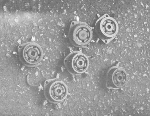
Fig. 1: 5-pin breadboard sockets for mounting on wood were purchased at the Southern California Antique Radio Swap Meet. The dark background is the asphalt pavement where they were laid out and photographed.
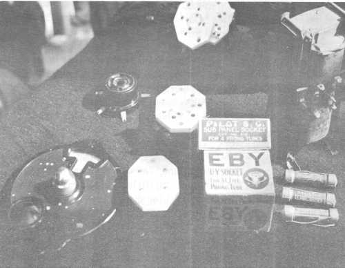
Fig. 2: Some other items purchased at the Swapmeet. The very brilliant white items are Hammarlund tube sockets. New EBY and Pilot breadboard sockets are still in the original boxes. Above the dial is a new Pilot 5-pin breadboard socket. The dial, a National type B Velvet Vernier has spots of paint which should come off easily. On the right are some IRC metalized resistors and a B battery eliminator filter choke assembly.
TO BE CONTINUED NEXT ISSUE
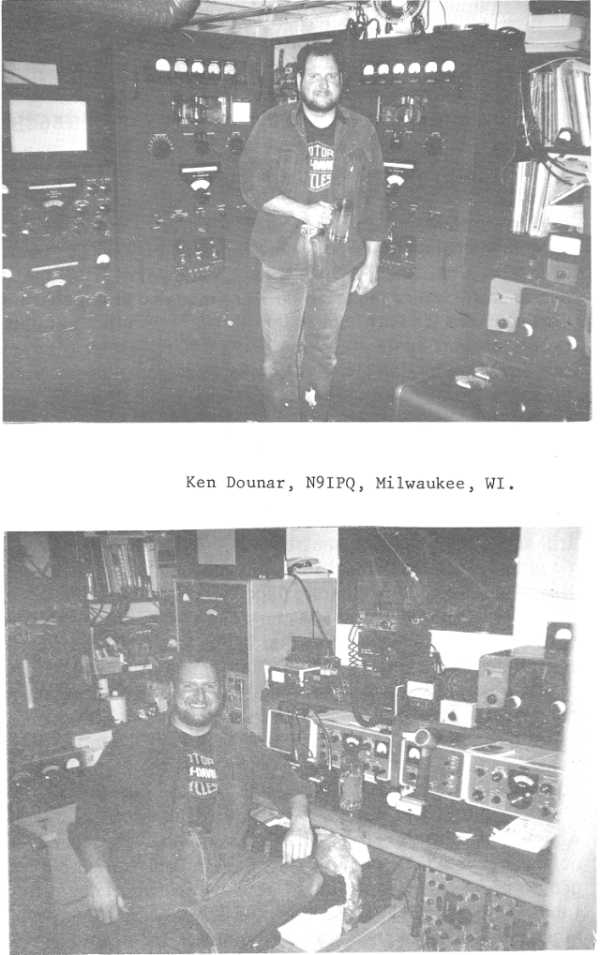
MEET the AMers
THE SELF-MODULATED SCREEN GRID
Bacon, WA3WDR, 8 Paulding St., Huntington, NY 11793
Most amateur AM transmitters in the 50 to 200 watt class use plate-modulated tetrodes and feed the screen grid through a series dropping resistor from the modulated plate supply. Examination of the modulation linearity of this design shows a kink at about 85% negative.
Dean, WA1KNX, found a way to eliminate that kink by feeding the screen from a resistive voltage divider providing less modulation to the screen than to the plate. I tried that, and it worked for me, also.
Then I read about the effect of plate voltage on screen current. With a given voltage on the screen, when the plate voltage is high, the screen does not catch as many electrons from the cathode, because the strong attraction of the high-voltage plate snatches most of the electrons away. When the plate voltage is low, the screen catches more electrons from the cathode, because the low?voltage plate is not attractive enough to snatch as many electrons away. The screen will draw LESS current when the plate voltage is high, and MORE current when the plate voltage is low.
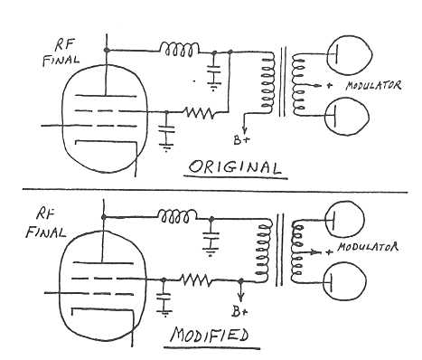
It looked as though a resistive screen supply ought to sel-modulate in phase with the plate without connection to the modulated plate supply. I tried this in my Viking II - I simply connected the screen dropping resistor to the unmodulated side of the modulation transformer secondary, and it worked! The kink was gone, and modulation linearity was excellent. This simple change can be done In any of the screen-dropping-resistor rigs such as the Apache, DX-100, Ranger, Valiant, Viking I and II, etc.
Another advantage of this arrangement is that the screen current comes directly from the plate supply, and not through the modulation transformer. This is an improvement, because it reduces the amount of modulator power required, and it reduces the amount of DC flowing through the modulation transformer secondary. No new parts are required; just move the screen dropping resistor from modulated B+ to unmodulated B+ (the other side of the modulation transformer secondary winding). It's not "something for nothing" - it's the elimination of a wasteful design mistake!
By the way, this self-modulating phenomenon is also how the "screen choke" modulators work: a change in the current flowing through an inductor causes a change in the voltage appearing across that inductor. An Interesting factor appears here, though: the higher the frequency, the more voltage will appear across an inductor for a given change In current through the inductor. How is it, then, that the screen is not severely undermodulated at low audio frequencies, and severely overmodulated at high audio frequencies?
The answer is that the screen current varies in such a way as to
"force" the voltage towards where the screen "wants" it to
be! If for some reason the screen voltage would start to go too HIGH, the
screen would draw MORE current, and the voltage would go DOWN. If the
screen voltage would start to go too LOW, the screen would draw LESS current,
and the voltage would go UP. This negative feedback action compensates for
the effect of reactive impedance over frequency and produces very accurate
screen modulation with either the resistive or the inductive technique.
SPAM
Amateur Radio at Its Finest
Post Offlice Box 27
Potrero, California 92063
Safety First
How sad it was to read about the passing of W2WME. He was electrocuted while working on his amplifier. Working late into the night, we sometimes forget just how dangerous some of the equipment can be if we are not careful. I have had my fair share of near misses; most have come when I should have gone to bed hours before. This kind of thing doesn't just happen to appliance operators, it can happen to anyone. Ralph will be missed by us all. We should not forget Ralph, or how he died.
10/160 Meter Jamboree
Sounded like many folks had a good time during the jamboree. Stations were wall to wall on 10 meters just about all four days. So far the two top stations are N4VMV Wayne Medley with 486 points and K4UOR Harry Bridges with 231 points. If you haven't sent in your results you should do so now. VE3CUI stated that that Electric Radio had a 20 meter contest running at the same time which he felt was confusing. We will try and make sure Berry gets a copy of the Jamboree calendar.
Welcome New SPAM Members
Thomas E. Jurgens KY8I Bridgeport, Michigan
F. De Silva CT1AXG Ovar, Portugal
Bill Bogart KA9CWK Covington, IN
Henny Heidtmann N4VHK Winston-Salem, NC
Nathan Moritz KD0MK Rapid City, SD
Donald Boland N1FYX Malden, MA
Welcome the above amateurs who are our newest SPAM members.
I also received from down under 6 pages of logs, and from the looks of it, this station must of worked most of you. Keith Richmond VK4XG Mt. Gravatt, Australia has started his own AM Society. The group meets on 75 meters on 3.580 mhz at 7:30 GMT each Tuesday. He has 6 to 8 stations check in and its growing.
EXCHANGE
FOR SALE: HT 32 $100; HT 37 $100; Gonset VHF linear model 3063 $100; BC221 with enclosed power supply $40; Yaesu phone patch for 301 $40; tubes type 813 $15 each; 805 $15 each; WANTED unique wire tuner, quotes on all Collins AM and S Line. Buying Collins 32V 2 or 3, NCX3 a.c. power supply
FOR SALE: Drake 2B w/manual $140, best audio quality, engineer/musician aligned, gladly deliver Dayton Hamvention.
WANTED: Pre-war FCC amateur Radio Licence application form, blank or otherwise.
FOR SALE: TCS power plugs (transmitter only) $5.00 postpaid.
WANTED: Old time pushbutton a.c. light switches and cover plates. Pre-WWII
U.T.C. transformers, LS or PA series with cast iron cases or end bells. What do
you have? I might even be interested in burnt-out transformers for the cast iron
parts.